


Technical Articles
14.07.20
The origins and future of industrial floor specifications and standards
Early days
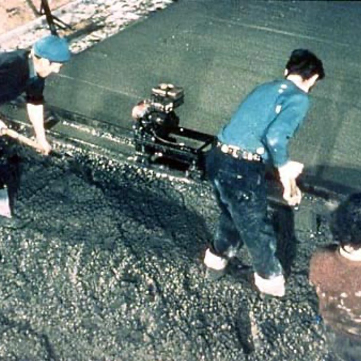
There was a time when the design and construction of industrial floors was simple. If the loads on the slab were light to medium, 6” of concrete and a single layer of mesh. If the loads were heavy, use an 8” thick slab with 2 layers of mesh. Specialist flooring contractors were yet to exist, and the construction was generally let as part of the groundworks package. During the 1970s, things began to change. Construction methods developed with the adoption of hand-screeding or flood-pouring, allowing larger areas to be cast in a single day. Concrete contractors, especially in the USA, started to become a recognised skill. As areas increased, so did the risk.
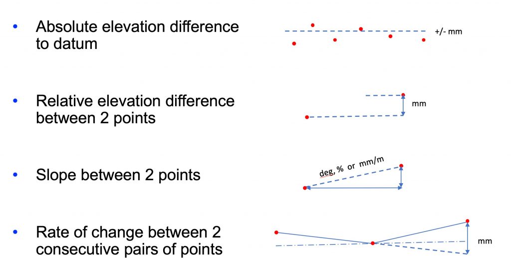
The supply chain for an industrial building is complex, with several stakeholders each having their own interests. Those constructing the floor are somewhere near the bottom of the pile and often, any excuse is used to have payment withheld against them. If cracking is not the problem, next on the list of complaints is flatness. In order to protect themselves, this burgeoning industry of concrete flooring contractors needed a way to define surface propertied contractually. In 1979, Allen Face developed the Floor Flatness numbering system, more commonly known as F numbers, which would later be formalised into ASTM1155. Now, quality could be defined, allowing not only the contractor to get paid but also the client to know what they were getting.
While F numbers worked well for defining the performance of free movement floors, VNA trucks, working in facilities with higher racking and narrow aisles, had different and specific requirements. Fmin, measured using a rolling profileograph, became the first defined movement specification.
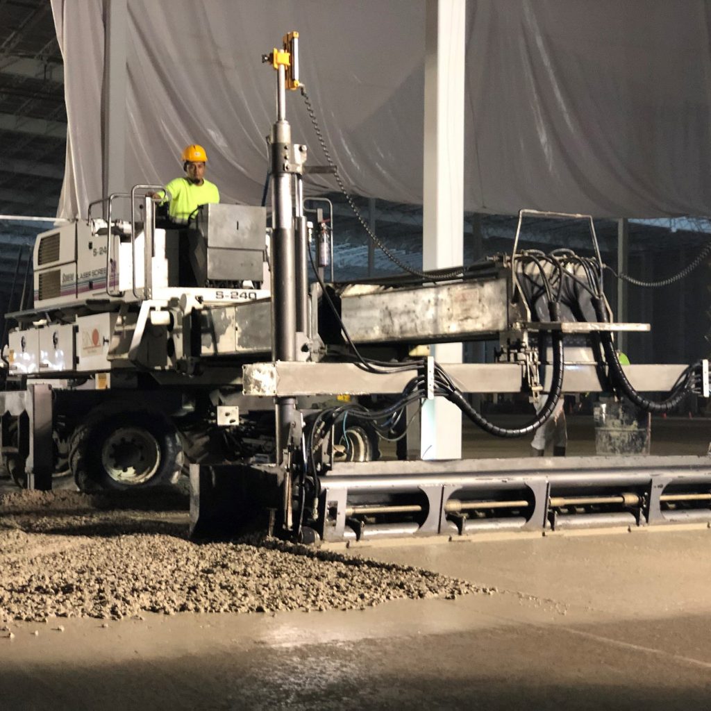
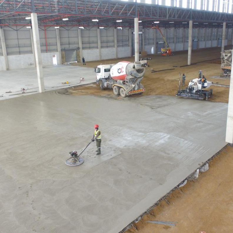
In 1987, the British Standards Institute published BS8204:2. This document defined categories of flatness using a straightedge test. Shortly after, The UK Concrete Society published its first edition of Technical Report No.34, bringing together guidance for the design and construction of industrial ground floors. Around this same time, Somero introduced the Laser Screed to market, changing floor construction across the world in the years that followed. Except for defined movement, where long strip construction is still commonly used, large-bay construction became the norm. The UK Concrete Society published TR34 edition 2 in 1994, later followed by an addendum, recognising the changing nature of floor construction.
Today, around the world, there are many standards defining surface regularity, including: VDMA, DIN-15185, DIN-18202, EN-15620, ICI 05-TC/09, NZS3114, etc. While generally suitable for the purposes they were written, most have been biased toward one stakeholder or another, be it the flooring contractor, testing house or materials handling equipment manufacturer. The stakeholder that is rarely represented, is the operator of the building. The entire industry is built around contractual compliance, not optimising performance.
Arguably, dependent on the stakeholder’s perspective, the vagaries in many of the standards are there for contractual protection or exploitation. The surface profile of a floor moves over time, either from curling at joints or deformation under load. From the flooring contractor’s standpoint, the floor was laid to specification. From the MHE supplier’s perspective, the trucks can’t run at full speed because the floor doesn’t meet specification. Timing of testing is critical.
While this is particularly critical for VNA defined movement floors, ultimately the errors can be identified, and rectification undertaken. This generally takes some form of grinding, although there are several coating options as well. If grinding is undertaken, it must be for a sound reason and not just to meet specification to within fractions of a millimetre. As soon as you begin grinding, you are disturbing the integrity of the surface finish.

When it comes to random traffic floors, the vagaries are even greater. Understandably, due to the laborious nature of measuring and collecting data, only a sample is taken. It is argued, statistically this provides a good representation of the quality. The reality is that for standards such as ASTM1155, TR34 and DIN18202, less than 2% of the total floor is sampled. As the exact locations of are not defined, it could be imagined that the flooring contractor may influence where the sample lines are taken, thereby assuring specification is met. Equally, the engineer surveying the floor has some freedom to select areas to demonstrate the floor does not comply.
The big question then becomes, where is the non-compliance and how it going to be remediated? Generally, what happens is payment is either delayed or discounts are negotiated. Some standards even lack a 100% limit, instead only defining the 95th percentile. Technically you could have a few house bricks on the floor and still pass specification, especially when you consider that such a small sample of measurements has been taken. If a conflict arises and the floor is retested, with the possible effect of time, location of measurements, methodology, instrument, etc., the probability of achieving identical results is low.
Looking to the future
While expressing reservations about some of the current standards and specifications, they have generally served us well from both a construction perspective and building owner/user. However, with increasing automation and deployment of robots in logistics centres and manufacturing plants, the requirements placed on the floor are changing.
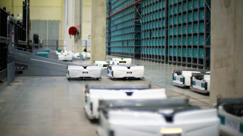
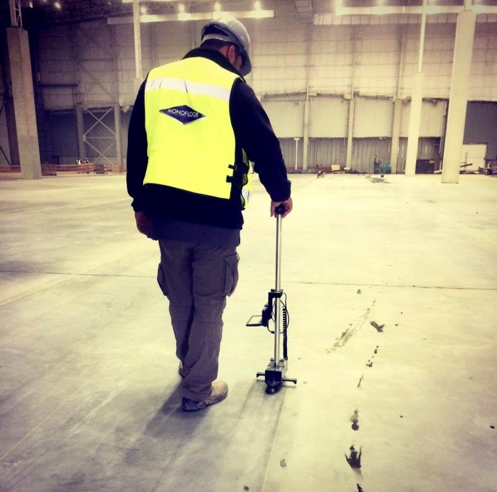
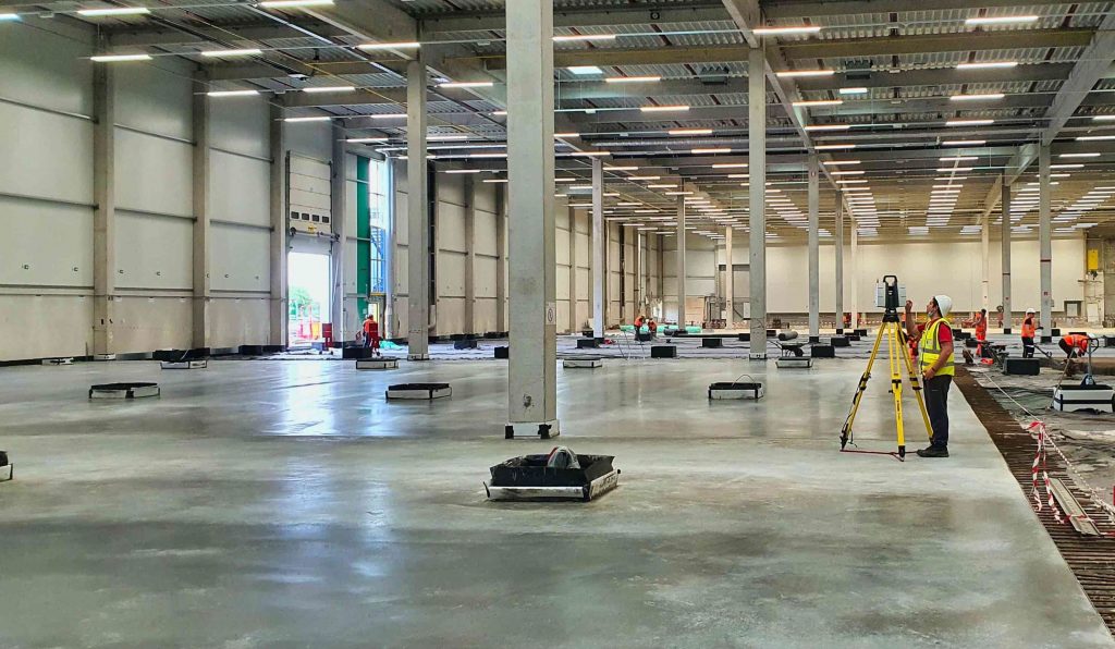
These robots can run anywhere on the slab, either on a defined grid or in a random pattern. The first consequence is that the floor surface regularity must be consistent across the entire area. Using surveying techniques that measure only a very small sample to check for conformance, are inadequate. The building operator will be left to identify and rectify problem areas during operation, adding huge and unnecessary costIt is possible to profile the entire surface of a floor. ASTM1155 was updated in 2014 to allow the use of 3D laser scanners to measure F numbers.

There is currently much debate and resistance to the adoption of this technology. Firstly, the methodology and equipment used has been poorly ported across from the world of BIM. In the world of industrial flooring, we are measuring and reporting to millimetre, and even submillimetre precision. This can be achieved, but only using survey/engineering grade scanners, with rigorous processes in place for collecting and analysing the data.
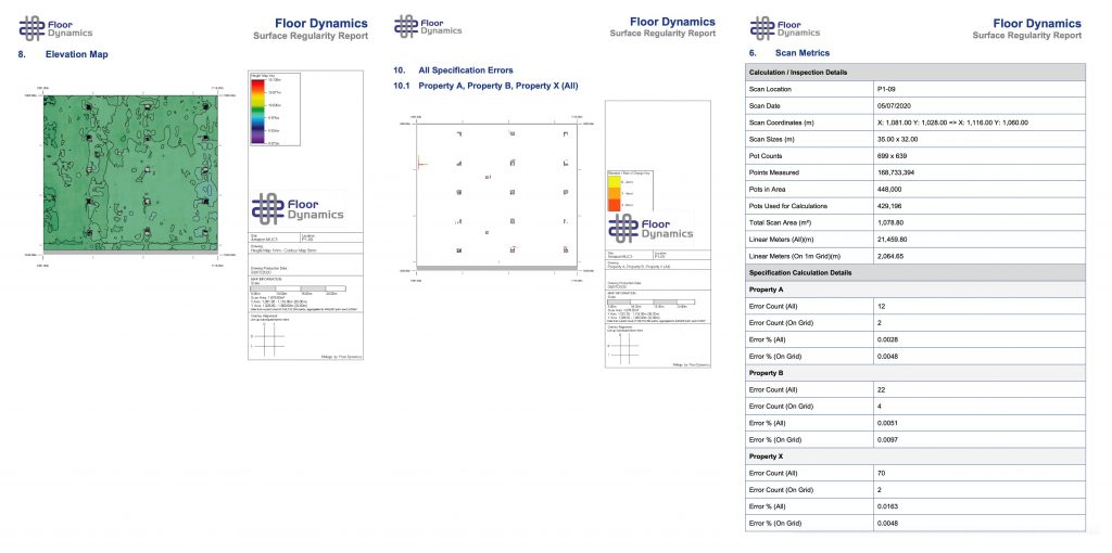
Just as importantly, there is a considerable lack of knowledge and ability to interpret the data. This again, can have contractual consequences. A flooring contractor may be contracted to construct a floor to FF35/FL25. The GC, engineer or client, may commission a local surveyor to measure conformity using a laser scanner. The result may demonstrate compliance, but the surveyor issues a report containing a pretty and colourful heat map. It may look impressive, but the red zones are an immediate source of conflict. From the flooring contractor’s point of view, they have delivered what is required. Remember, ASTM1155, even when measured using a laser scanner, is only calling for a very small data sample. Interpretation is often guided by who is paying for the survey.
Progress is being made in understanding the curvature and waviness profile of the floor surface to enable efficient running of various types of autonomous materials handling equipment. Today, however, a detailed understanding of dynamic behaviour of these vehicles is lacking. Once this is better understood, operating speeds can be optimised, and greater efficiencies achieved. Now that we have the ability to create high-definition maps of the surface, we are a step closer to being able to define performance-based specification.
Meanwhile, the flooring industry needs to be educated into accepting that construction of floors for automated logistics systems does not require unrealistic super-tight tolerances. They do, however, require consistency and uniformity that is stable over time. This may require adopting different techniques not only for placing and finishing, but also quality management, mix design, etc. Surveyors and consultants need to be able to supply reliable and trustworthy reporting, based upon defined standards for collecting data using laser scanning. The results must be consistent and reproducible. Finally, contracts need to be agreed with all parties that are based on optimising performance of the materials handling system, and, an agreed method of rectification for when errors do occur. This is a new chapter in the industrial flooring journey, yet to be written.
Andrew Keen – CSO RCR Flooring Services