


Technical Articles
13.10.20
Laser scanning – pretty pictures or High Definition Mapping?
There is currently much debate about the validity of 3D laser scanning as a method of measuring floor surface regularity. Papers have been published1,2 of studies concluding that the use of terrestrial laser scanners (TSL) can generate information of the calibre and quality required for analysis of substantially flat surfaces. However, their use as a method for calculating F numbers in accordance with ASTM 1155, has left much to be desired. Aside from the lack of correlation between results obtained from TSLs and other methods, such as the Dipstick, the surveying industry has adopted the practice of producing elevation heat maps. This has led to the rather derogatory, but perhaps deserved expression, “nothing more than pretty pictures”.
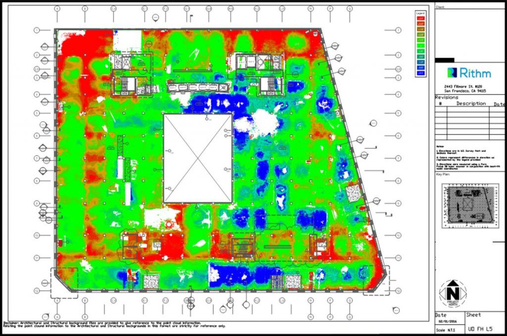
To give a broad view of the overall surface profile, showing for example, where ponding may occur, these heat maps are more than adequate. For any further analysis, their value is limited, and the information derived can lead to bad decisions.
In a previous article, I have described the different categories of laser scanners available. These range from simple, easy to use scanners more than suitable for basic BIM work, through to high end metrology grade scanners costing hundreds of thousands of Euros/Pounds/Dollars. Ultimately, however, a laser scanner is nothing more than a tool to collect data.
At Floor Dynamics, we have spent over two years, and a considerable investment in learning how to produce high-definition maps. From these maps we are able to read elevation with reference to datum, difference in elevation between discreet point, and curvature, or rate of change in elevation. Think of what we are producing as a 1:5k ordnance survey map in comparison to a 1:100k road atlas.
A laser scanner is just one of the tools or instruments we use to produce these maps. To use an analogy with another type of instrument, a piano for example. I can pick out a tune using a couple of fingers. You may even be able to recognise it. It wouldn’t really matter if I was playing a $200,000 grand piano or a $500 keyboard. The result would be the same. Now imagine a concert pianist.
While they would undoubtedly play the cheap keyboard way better than me, the detail they could extract and the music they could produce from a grand piano, would be in a different league. In learning to play, good technique is critical. To play in time and to a particular beat, you may use a metronome to provide calibration. For all but the very best concert pianists, a $200,000 grand piano would be overkill. Aside from the talent of the player, only the most discerning of ears would be able tell the difference against a model costing $10,000. There comes a point where ‘good enough’, although not perfect, is sufficient.
High Definition Mapping
Without giving away too many trade secrets, the key elements of producing HD maps include:
- Establishing an accurate control network
- Close centre, high resolution scanning
- Production of calibration grid
- Precise registration of multiple scan positions
- Processing of point cloud through Pellego™
- Interrogation of Pellego™ HD maps against specification
- Reporting and visualisation of data.
The data is collected using an engineering grade TSL with dual axis compensator, a 0.5” total station and a digital level with high precision invar staff.
It goes without saying that rubbish in equals rubbish out. The collection of sufficient and high enough quality data is the first step. Not only the choice of instruments, but also the process, or workflow, is critical. The surveying industry, in general, doesn’t practice the skills that are required to collect the quality of data we need. This is for the simple reason that the demands of their regular work are different to what is required for HD mapping. There has not been a need until now.
Once the data has been collected, it is then processed. Dependent on the software and equipment used, the production of a unified point cloud may use auto-registration of individual scans. More commonly, commercial software packages allow for various types of manual, or semi-automatic registration. During this process, a significant amount of cleaning normally takes place. The cleaned data is then decimated and meshed to produce a surface from which measurements are then taken.
This process eliminates and smooths the data. As such, it loses definition and accuracy. Think of it as taking a high-resolution photograph and converting the file to a small jpeg, suitable for posting on social media. Viewed on a phone or computer screen it will look fine. If you try to produce an A3 print from the same file, there is nowhere near enough information to render a half decent picture. Not only are there not enough pixels, the data will be using a reduced colour spectrum.
Pellego™
To overcome the limitations of commercially available software for manipulating point clouds, Floor Dynamics developed Pellego™. This software is lossless. In other words, it is using all of the raw data. To return to the photograph analogy, we have high megapixel, high bitrate file produced from a quality DSLR camera using a high-end lens with inbuilt stabilisation – not a cheap phone camera. As with cameras, the number of pixels (data) alone, does not necessarily guarantee the quality of the picture.
The pixel size Pellego™ uses to generate its HD maps is 50x50mm. Each pixel, or pot as we term it, contains on average around 325 individual lidar points. The image of 40,000m2 floor, typical of a robotics logistics centre, contains 16 million pots/pixels generated from 5.2 billion individual pieces of data. Each of these pots/pixels, is assigned a z value based upon the information contained.
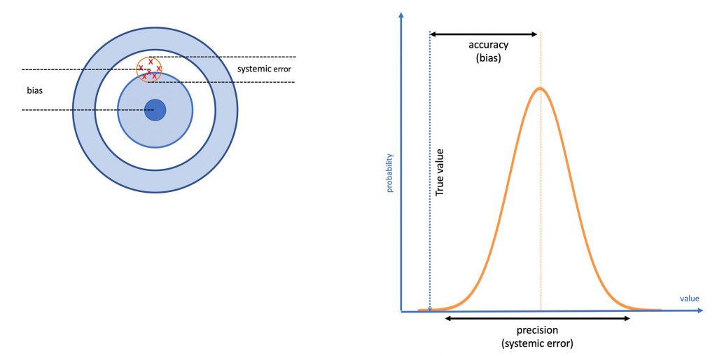
In a previous article I have discussed terms such as accuracy and precision, both of which are elements of an error. With enough data points within each pot and calibration against another data set (instrument), we can calculate the systemic error and bias. As a result, the confidence in the trueness of the assigned Z value is increased, ie: the uncertainty decreases.
Once the HD map has been produced, calculation of conformance against a particular standard is a process of comparing the Z value of one pot to that of another.
An alternative used to extracting values from a meshed surface in commercial software, is to take the values of individual lidar points closest to a given x, y position. The problem with this methodology is that you have no idea where on the distribution curve these points fall. It is this high uncertainty from taking an individual reading, or using smoothed data, that gives rise to the intense debate about the accuracy of laser scanning.
Visualisation of data
The way that data is visualised is imperative to its understanding. We all know that the perception and meaning of a graph can be altered simply by changing the axis units. Colours also play a vital role. In most cultures, red signifies danger. Factors such as these are also responsible for the criticism that laser scanning is great, if you only want pretty pictures. It is not uncommon for disputes to arise between contractor and client where a floor passes F number specification, only for the client to more focussed on the big red patches on a poorly produced heat map.
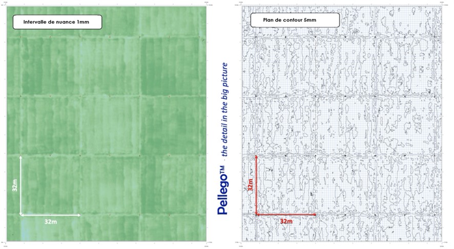
Putting aside all the technical arguments over which type of scanner to use and how accurate, or not, they are, fig. 4 shows a couple of maps from a recent project. The floor was measured for conformance to Concrete Society 4th edition FM2. It’s a good floor – jointless panels of 1024m2. What is amazing is that in the left-hand map, the shaded stripes that are clearly visible are caused by the pull of the Laser Screed. There is a minor elevation difference of 2-4mm over the 4m width of the screed head (a slope of 0.05-0.10%). If you zoom in on the original file, it is even possible to see the impact of variations in slump of concrete loads in some areas.
Visualising the same data in a different way, such as the 5mm contour map on the right, other characteristics become more prominent. It is very clear where the construction joints are. As the floor was mapped some time after construction, what we don’t know is what caused this. This result could be caused by construction factors such as joint installation, or the way in which the edges are feathered in by hand. Alternatively, curling could be a contributor. If the floor was mapped during construction and then again at some months later, this can be measured.
Floor Dynamics employs laser scanners, as one of the tools, to collect data in order produce High Definition mapping of the surface. It is not a laser scanning company. The resulting output is very different. HD mapping yields a whole world of valuable information in order to continuously improve construction quality. The result of which is particularly important in the performance of automated and robotic logistics facilities. Pretty pictures, or HD maps that contain a wealth of valuable information? You can be the judge.
Andrew Keen – CSO RCR Flooring Services
References:
William Paul, James Klinger, and Bruce A. Suprenant, “ASCC 3-D Laser Scanning Study, Part 1: Eight participants used scanners to determine target coordinates” Concrete International Journal – Jan 2019.
William Paul, James Klinger, and Bruce A. Suprenant, “ASCC 3-D Laser Scanning Study, Part 2: Eight participants used scanners to determine F-numbers” Concrete International Journal – Feb 2020.